While BIT 1.36 V3 is still active and ready to compete, I started on BIT 1.36 V4. As I am getting more comfortable with some complex designs by building the previous 3 beetles, I hope I can go for some more ambitious and competitive designs in the fourth robot. I hope that the robot can stay largely the same as the previous ones concept-wise and focus on internal improvements. The design goal of the new robot will stay consistent with the previous robots.
compact
durable
stable
cheap
creative
maneuverable
fast
destructive
Some specific design features that I would like to try this time:
Hubmotor drum that reuses the old drum from last robot
Custom 4 wheel drivetrain setup similar to BIT 1.36 V3
6s battery
Return to 7075 aluminum frame
A wedge for horizontal spinner
So we are going to go over each of those features
Frame
On the last robot, I tried a UHMW frame for the first time. Strength-wise it is satisfactory, only suffering from cosmetic damage, but there are some disadvantages:
Heat set insert does not work particularly work well with UHMW
The frame rail is very thick, taking up quite a lot of space
The holes in UHMW for plastite screws can strip over time
Not suitable for the hubmotor drum design I had in mind (I will elaborate later)
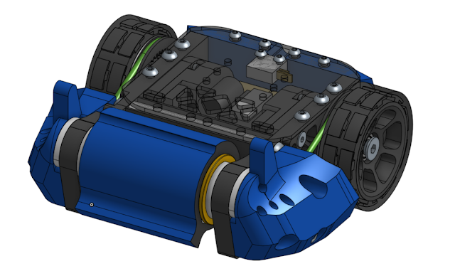
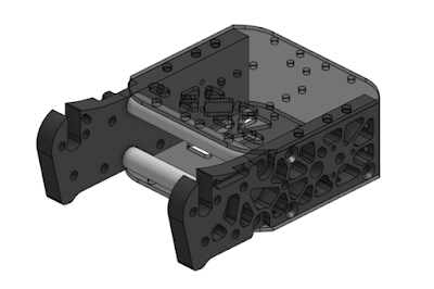
I decided to go with a beefy 3/8" 7075 frame, with M6 aluminum standoffs connecting the two billet frame rails.
The top and bottom plates are carbon fiber just like V1 and V2, but one thing I did differently was that I greatly reduced the amount of pockets on the plates. This is because of the following reasons:
The weight reduction is in fact not as significant as I thought
V2 and V3 both had a match where the top plate was almost penetrated
Less exposed electronics
Increase cost significantly
Allows me to manually drill holes where I need them to be without worrying about the pockets
3/8" 7075 aluminum is quite a lot thicker than V1 and V2 where I used 8mm 7075. This weight needs to be compensated by more aggressive pocketing. I believe that this will in fact end up yielding higher strength because the thickness of the material plays a bigger role in preventing deflection than the width of the plate.
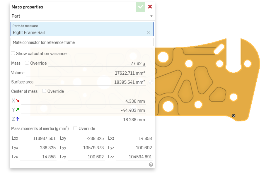

Through pocketing we are able to save 20g on each side, which is extremely valuable as it saves weight for attachments that allows us to counter specific types of robot depending on the opponent.
The two aluminum standoffs between the two frame rails are VERY important. It takes stress away from the top and bottom plates, which are not supposed to be structural. I learned this lesson the hard way at my first beetle event, where the whole side rail of the robot was torn off by a horizontal spinner.
Drivetrain
The drivetrain concept worked very well in V3 and I would like to stick with a similar design.
Enclosures
Due to how thick the UHMW frame was in V3, I was able to sink the gears of the gearbox into the frame rails. There are some pros and cons:
Pros:
Save space
better enclosure
less part count
Cons:
Bad accessibility
requires pockets on the inside of the frame, so if there are any features needed on the outside, we would need to flip the part on the router, which adds complexity.
This time, due to the thinner aluminum frame, there is simply no space for me to sink the gear into, so the gear has to be covered by another part.
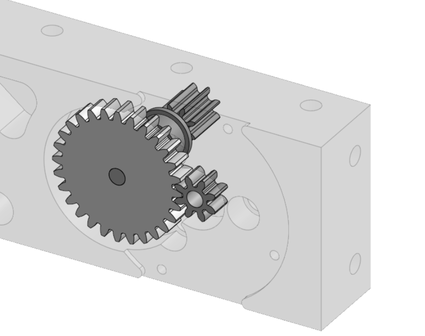
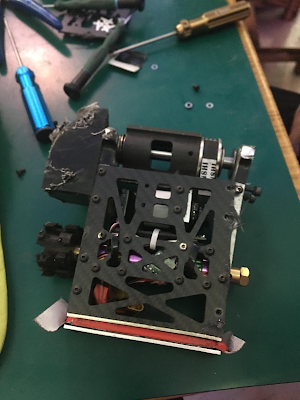
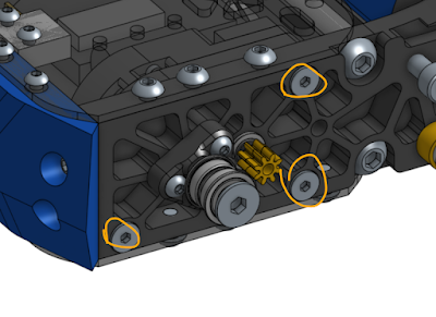
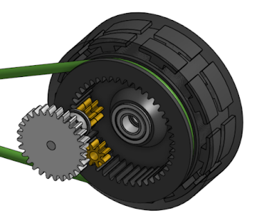
V3
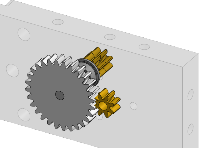
V4
As you can see, the two designs use a very similar setup. We would need some other sort of enclosure for the V4 gearbox. v3 never had proper enclosure, and metal shavings from the gearbox can be seen through the polycarbonate panels. Although they never actually got into electronics and mess things up, it is a big concern.
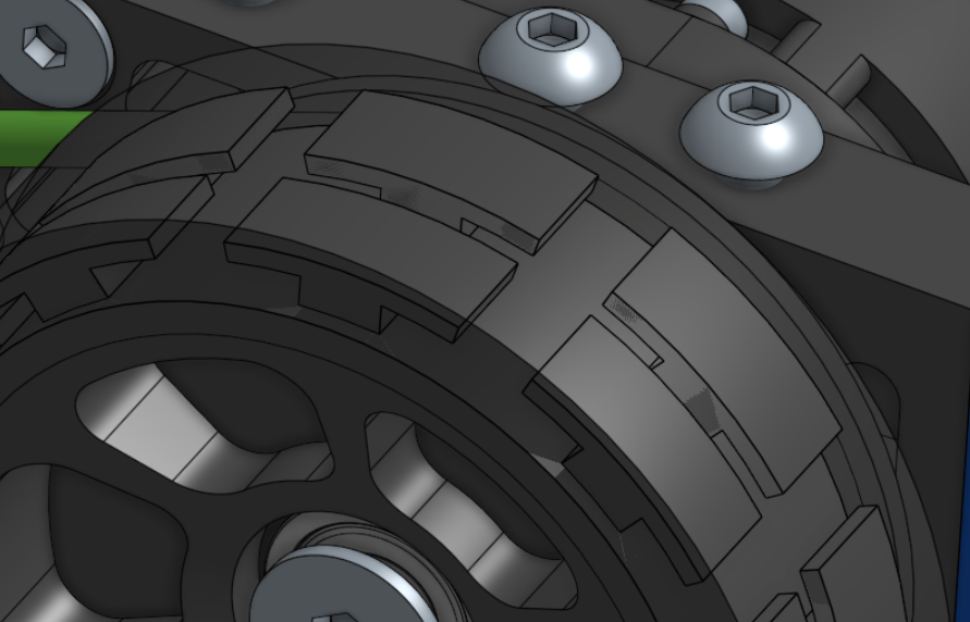
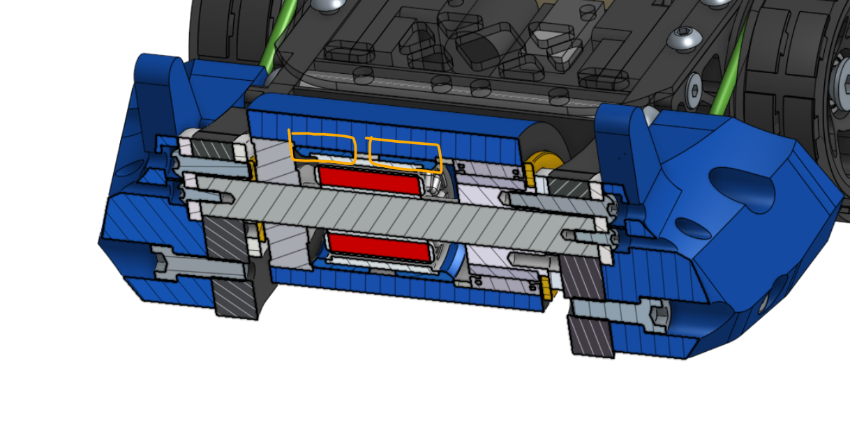
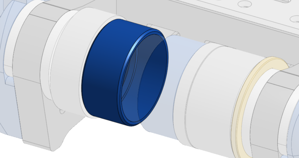
I decided to use a two part enclosure. The first piece serves as the motor mount and partially covers the gear; the second piece serves as a ESC mount and covers the motor and the rest of the gear.
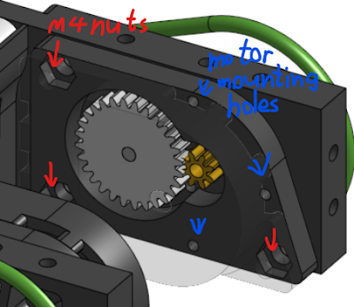
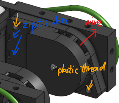
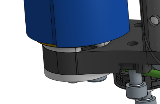
The enclosures are held on by three countersink bolts on the outside. The first layer is held on by nylock nuts while the second layer is held on by plastic thread. This is because the first layer takes more load as it serves as the motor mount.
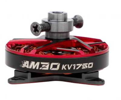
Motors
The motor I am using is T-motor AM30 1450kv, just like V3. The stator size is around 2504, quite enormous for a 3lb machine, but it is truly one of the flattest motors you can find on the market. It has several features that makes it good for the drive motor:
Mounting holes are very far apart from each other and very accessible
4mm titanium shaft stepped down to 3mm in the front
11mm thick in total
The shaft collar for propeller mounting can be taken off unlike some motors where the collar is built into the rotor (such as sunnysky F3P motors).
If you want the shaft to come out from the mounting side, you can press the shaft out and push it back in the other way.
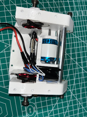
(Prototype made during V3 build)
However, when doing those shaft modifications, we need to make sure that we are not damaging the rotor in the process and the force pressing the shaft in and out is parallel to the shaft, otherwise the rotor may deform and end up rubbing the stator and causing problems. To achieve this we need a jig.
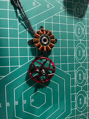
(Taking the motor apart)
(3D printed jig that holds the shaft in place)
(rotor with inverted shaft)
Gearboxes
As for the gearbox, I used aluminum gear to replace the steel gears for weight saving. The gears are 0.8M 28 teeth.
The second stage of the gearbox involves a ring gear that is built into the wheel hub. The design intention is that under load and deformation, the gear in the second stage would simply skip to reduce the load on the motor and prevent force from going into the gearbox.
The 64D TPU ring gear was mildly too soft in my opinion and sometimes it skips more than I would like, so this time I want to use 72D TPU, which is even stiffer.
The two stages altogether should yield about 19.25:1 gear ratio. Under 6s with 1450kv motors and 58mm wheels, that should give us:
1450kv*24v*58mm*3.14/19.25=330000mm/min=5.5m/sec
This is totally satisfactory for a 3lb robot.
Rear Wheel
I am using a dead axle setup for the rear wheel because it is a lot easier to retain the bearings and shaft. The shaft is a 12.9 grade M6 countersunk bolt. The frame rail is threaded and an extra nylock nut is installed on the inside to prevent the bolt from backing out. A 3D printed part is used to hold the nylock nut in place. So the idea is that the thread on the frame rail will limit the axial movement of the shaft while the nylock nut will limit the rotational movement.


The wheel tread will once again be molded silicone. We have got a molded silicone wheel dialed in since V2 and it has not let me down at all. The hub interface pattern has been quite strong and allows me to make the tread quite thin. The thinner the tread, the lighter the wheel is. The idea is that the compliance of the wheel can be provided by the TPU hub so it is okay to have the tread thinner than usual. Plus, the impact on the wheel will barely go into the gearbox because the ring gear can simply skip to limit the torque going into the gearbox.
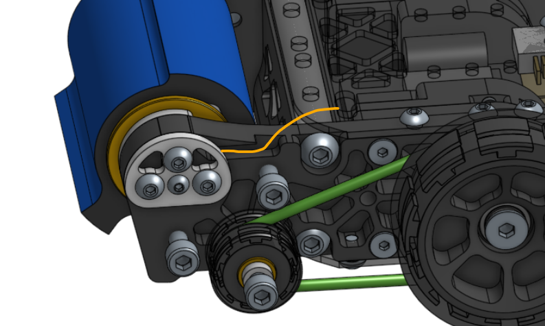
Front Wheels
Since V2, I found it quite helpful to have a pair of front wheels so that the front of the robot does not drag on the floor. In V3, due to the center of gravity being so far front, the front wheel is actually taking more weight than the rear wheels, and the texture of the front wheel really affected the performance. This is why this time I decided to use molded silicone for the front wheels as well just like the rear wheels.
Just like V3, I used 3mm PU round belt for power transmission between the front wheel and the rear wheels
I used to run a m5 titanium bolt as the front wheel axle, and it would bend under hits. This time I decided to do a m5 aluminum standoff here with graphite brass bushing around it.
Weapon
The weapon is really the biggest unknown factor in the design, especially the motor part and its TPU protection. I definitely need to do some adjustments when I receive the parts.
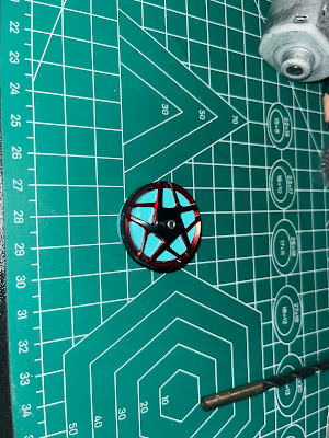
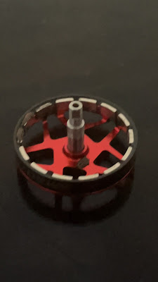
Drum
The drum is quite expensive to make, so I want to continue using the old drum from V2 and V3. The one on V3 has barely worn and the one on V2 is merely a little blunt.
The drum weighs about 340g and the material is 4340 steel hardened to 44 hrc.
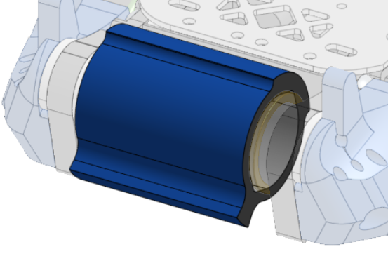
This used to be designed to attach to a pulley, so there are two notches for torque transfer. We will not be using this feature here.
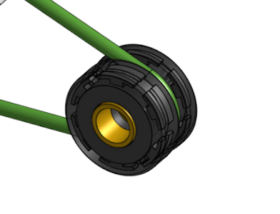
Bearing/Shaft
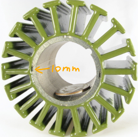
I decided to go with a 10mm hardened steel shaft for the weapon shaft because it has not failed in the past 3 robots.
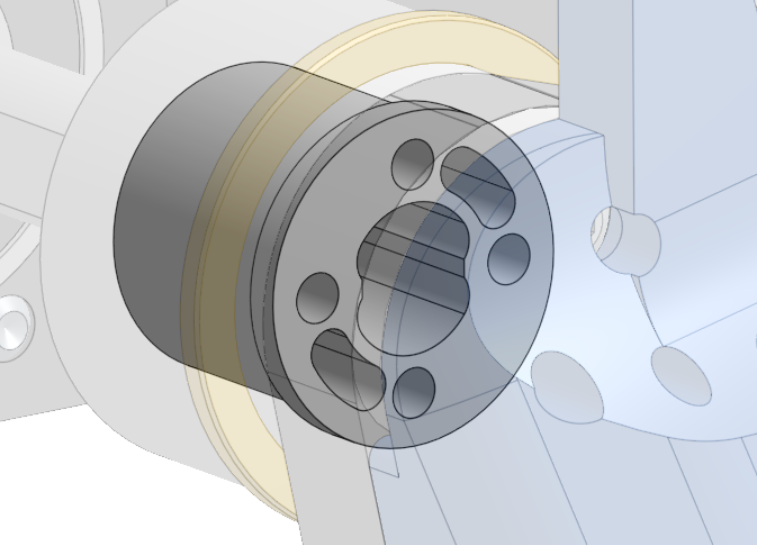
One of the design constraints is that the bearing needs to be very thin on the wire side. So the bearing hole is 32mm in diameter, the shaft is 10mm thick, and we need at least 10 extra millimeters of inner diameter on the bearing for the wire to pass through the shaft and the bearing. This implies that the bearing must have an outer diameter of 32mm and an inner diameter of at least 20mm. It is hard to find such size for ball bearings, and the load ratings for those are usually not enough. I found that my best bet is needle bearing. I have to use needle bearings along with a hardened steel inner race because under load, needle bearings can make dents on the part they are rolling on if they are not hard enough.

I eventually decided to use NKI 20/16 bearings (32mm OD, 20mm ID, and 16mm thick). The 32mm bearing hole actually goes 20mm deep, but NKI 20/20 (32mm OD, 20mm ID, and 20mm thick) are very overkill and heavy. Their load rating is 7400 lb on mcmaster while that of bearings I used on V2 and V3 is around 1100 lb.
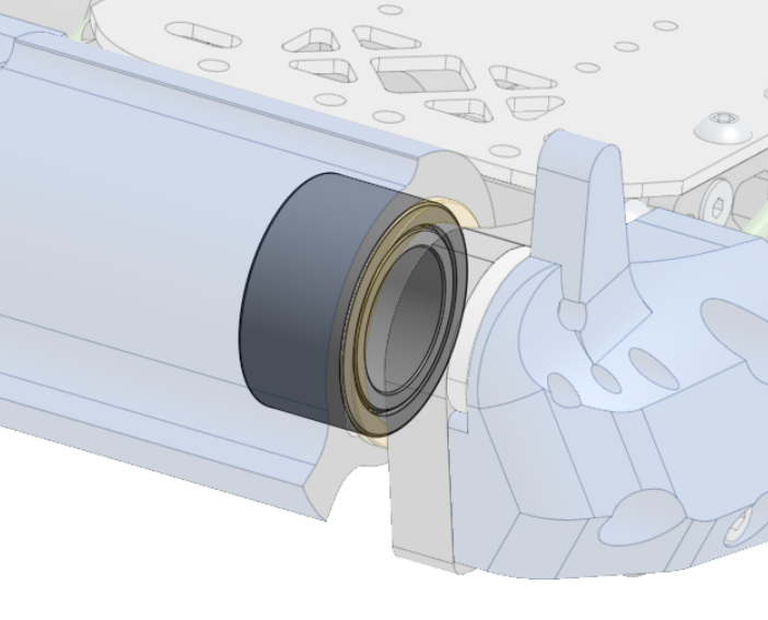
This does pose a problem where the hole is 4mm deeper than the thickness of the bearing, and we have to find a way to fill this gap. I ordered custom steel rings to go under the bearing to solve this problem.
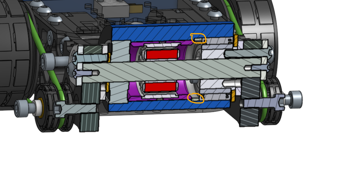
On the non-wire side, it is a lot simpler. We can use the same 10mm ID 32mm OD 10mm thickness bearing again.
I decided to make the shaft double D-profile because we have to ensure that the shaft does not spin when the weapon spins, otherwise the motor wire will get twisted.
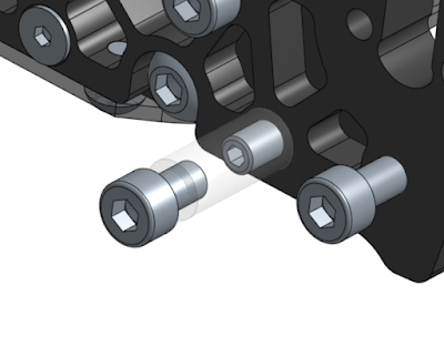
It is not hard to imagine that this will be very difficult to service. To make my life slightly easier, I decided to make the weapon shaft removable from the top. By removing the bolts outside the frame rails, we can slide the whole weapon assembly off from the top of the robot. Those bolts also take part of the sheer force from the weapon, adding some redundancy to the shaft. This is also why I don’t think a UHMW frame would be the best for this structure, as it lacks the rigidity we need here.
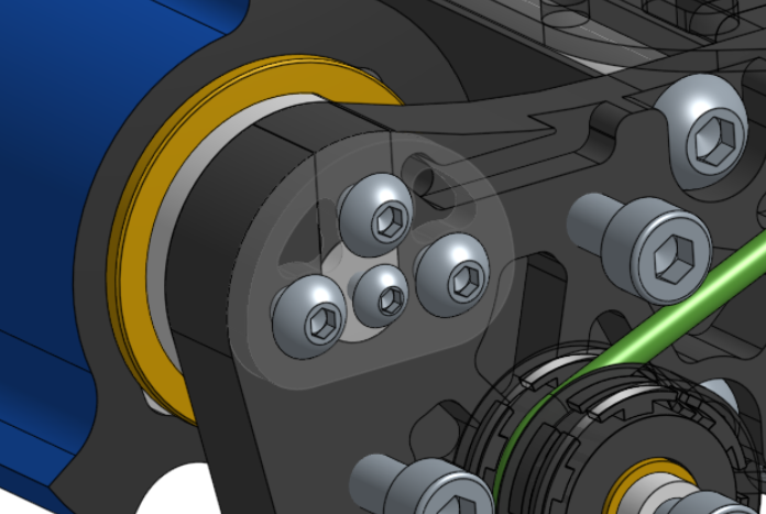
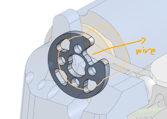
Weapon Hub
The weapon hub needs to do the following things
Fill the gap between the shaft and the bearing
Have holes for the wire to go out
I put two holes for wires because it can save some weight and provide some redundancy in case one of the holes is somehow damaged.
Retain the inner race of the needle bearing
I decided to have two tapped M3 on one side to retain the inner race. It shouldn’t be taking a ton of load.
Directly connect to the frame rail to reinforce the shaft and prevent the shaft from popping off from the top
There are 4 tapped M4 holes on the outer side of the hub that can be connected to the frame rail.
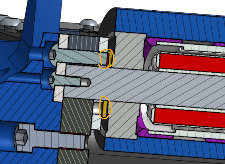
Provide axial support for the weapon
There is a brass washer outside the bearing to provide such support while having relatively low friction.
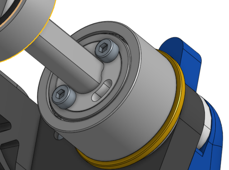
An aluminum spacer of 3mm thick is added to the outside of the weapon hub to create space for the motor wire to come out.
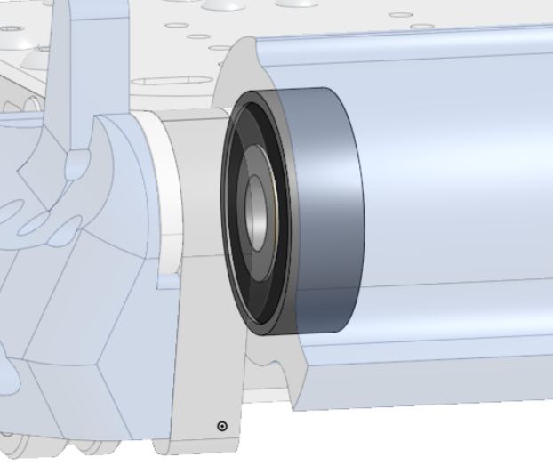
Since I can use the same 10mm ID 32mm OD 10mm thickness bearing on the non-wire side, no aluminum hub is needed between the shaft and the bearing. However, two parts to hold the shaft in place are still needed.
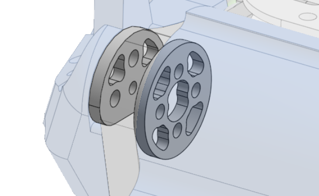
To provide axial support on the non-wire side, I added a small brass washer outside the bearing.
Motor
Due to the geometry of the drum, the can size of the motor is limited to <30mm. I would like to have it around 28mm to provide space for some shock absorption.
I have several candidates for the motor:
Propdrive 2836 1400kv
Flash Hobby D2836EVO 1450kv
SS Series H2223 with custom 1600kv
Hobbywing Skywalker 2316 1400kv
Hobbywing Skywalker 2320 1250kv
Sunnysky V3 2216 1400kv
Sunnysky V3 2220 1400kv
I ended up choosing SS Series H2223 with a custom 1600kv because:
It has the biggest stator size by far, and has a 27.2 mm outer diameter.
In theory, we can get a 260 mph tip speed on the weapon, which is more than satisfactory for me.
22mm stator diameter is ideal because all the 22mm stators I have seen have a 10mm inner diameter after removing the stator base. Certainly I am not 100% sure that it is the case for this motor, but they don't provide dimensions for it.
Cheap.
The air gap of the motor doesn’t seem to be too small.

Shock Absorption
Something I always wanted to try is using TPU between the drum and the rotor for shock absorption. A potential problem with this is that the concentricity of the rotor is completely dependent on the rigidity of the TPU. If the TPU is compressed, the Stator will rub against the Rotor. I believe that this can be mitigated in 3 ways:
Make the TPU layer very thin so that it can not be physically compressed to a point where it can cause a problem.
Use stiffer materials so that it is harder to compress.
Preload the material when assembling. It is harder to compress a part that is already compressed
I hope a combination of those three solutions can solve this problem.
Wiring
After going through the weapon hub, the wire will go through the frame rail and go into the robot through a hole on the top plate. I need to keep an eye on sharp edges that can potentially damage the insulation on the wires.
Electronics
ESCs
The ESCs we are using on this are identical to V3: DYS Aria 70A ESC as weapon ESC and two Cyclone 35A ESC as drive ESC. Cyclone is not a mainstream ESC brand but we have been using their ESCs since V1, and they make some very durable ESCs.

Battery
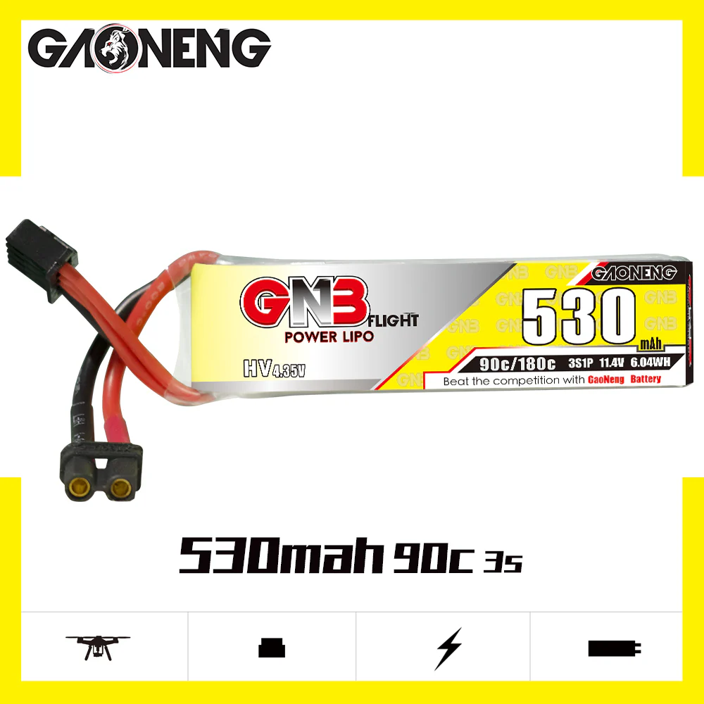
So on V2 and V3, I used Tattu 4s 750mah 95c batteries. They are more than enough for me. Since we moved on to 6s here, we can proportionally reduce the capacity of each cell. I ended up deciding to use two GNB 3sHV 530mah 90c. The reason why I need to use two 3s batteries instead of one 6s is because that seems to work the best for the layout.
BEC
None of the ESCs have built-in BEC so we have to get an external one. The iFlight 2s-8s micro bec seems very promising. It is very small and is made by a trusted company.

Receiver
For the past three robots, I have been using the FrSky XMR receiver.

They are discontinued and I think it is about time to move on from them. It is hard to find another D16 protocol receiver with PWM output this small. The alternative I found is the Radiomaster R84 receivers. They are slightly bigger than XMRs but are not too bad at all.

Power Filter Board
When motors experience huge load, it can cause fluctuation in voltage, partly because motor will send a pulse of back-EMF back into the circuit, and partly because the internal resistance of the battery will cause a voltage drop.
For the past 3 robots, we have been using 2200µF capacitors as power filters. They are quite big and there is a diminishing return in increasing capacitor size. This is why I decided to buy something specifically designed to do this job: RUSH PFB

Switch
For the past three robots, I have been using XT30 links as my switch. They work fine most of the time but I got my link cut off in two matches. So this presents a dilemma: If the link is not exposed, it is hard to access; if it is, it will be vulnerable to hits. This is why I decided to move on to Lynx anti-spark switches.

Summary
By the time this is written, all of the parts have been ordered. This robot sure contains some ambitious designs and challenging mechanical problems. I will keep you guys updated on how everything goes.
Comments
Post a Comment