It is the second year I start to work on combat robotics. I started planning Team BIT's sixth robot before the summer holiday and it would be the second beetle weight of the team. The first beetle was built during the summer holiday of 2020, and took part in the Second LRFT Combat Robotic Competition later that year. A lot of problem of the bot was shown during the fights. The new bot would still be a drum spinner. And hopefully those problems will be eliminated as I have improved the design of the new bot. I'll share some of the thoughts I had when I am designing the robot in this article.

One of the main problems of the last
machine was that the strength of the whole structure is way too weak, the only
connection between the two sheet metals that hold the weapon was two carbon
fiber sheets on the top and the bottom with a few bolts. When I was fighting
against Zero from Team Black Rabbit, who was using a horizontal spinner to
compete, the sheet metal on the side was almost ripped off. It was made of 7075
aluminum alloy, the thickness was 8mm. In theory it is strong enough, but it
was the whole structure that failed, which is a problem that can not be solved
by simply making the beams thicker. That is why this time I added another beam
to make sure that the tragedy won't happen again. The main structure formed a H
shape, which is pretty common among drum spinners. The beams are all 8mm thick
7075 aluminum alloy, The carbon fibre covers are 2mm thick. I drew some Pockets
and holes on the parts for weight reduction.
(how my robot looks like after the fight with Zero)

The layout of the electronics remains the
same as the last bot, and the configuration is the same as well, that is
because none of the electronics failed on the bot during the 5 fights it had.
It might not be as stable if I arbitrarily change something. Here is the
configuration of the electronics The battery is an ACE 4s750mah95c
battery. The ESCs for driving are Cyclone35a brushless ESCs. The weapon ESC is
a 50a Hobbywing Skywalker. The driving motors and gearboxes are the second version
of gear boxes from the captain of Team Scrap Iron. The weapon motor is a
Sunnysky 22-16 2600kv brushless motor.

(layout of the electronics)
The last robot had a
relatively light weapon, at about 250grams, that is why it didn't really
deliver any nice hits and the whole robot was only about 1200g (which is still
160 grams away from the limit). So this time I want to go bigger on the weapon,
and it is 340 grams. The last design has a lot of issue in many ways:
1. The bearing was way
too small, and the maximum load was so small that the bearings got stuck after
a few hits. I was known afterward that putting several bearings close to each
other in a row is actually inappropriate.
2. The weapon pulley is
glued to the inner wall of the drum by thread locker. It is really hard
(actually impossible) to replace the bearing after they are stuck.
3. The pulley is
mounted to the drum by set screws, which would effect the concentricity between
the pulley and the drum. And them set screws might come off due to the
centrifugal force and the vibration.
4. The pulley was
mounted so close to the tip that it can get hit easily.

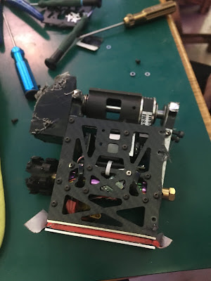
(picture of the last robot, you can see the existance of
the problems mentioned above)
Most of the problems have been fixed, the
bearings are replaced with two NMB deep groove ball bearings with an outer
diameter of 32mm and inner diameter of 10mm, supporting at the two ends of the
drum. And the holes for mounting the bearing have shoulders to hold the bearing
in place, so no glue is needed. The bearings are held by the shoulder and sheet
metal on the sides, and it makes maintenance easier. The pulley is lock into
the drum by a oval hole, which fixed most of the problems I had last time. To
increase the weight of the drum, I increased the diameter of the drum, the
pulley is further from the weapon tip, so it won't get hit so easily.

(weapon section view)
When the bot is flipped
up side down, it needs supports to prevent the weapon from touching the ground.
Some bots deliberately let the weapon hit the ground to knock themselves upward
to self-right, but I think it is a little bit unreliable, plus I am not really
a good driver. So I want my weapon not to touch the ground at all, and use gyro
effect to self-right. The last robot can self-right in less than a second, and
bought me a lot of time during fights.

I planned to use 3d printed moulds and silica
gel to make the wheels.The wheel hub is locked to the silica gel by T-shape
clips, to make sure that the tire won't come off. Normally the thicker the tire
is, the heavier the wheel is, because you can change the infill of the wheel
hub since it is 3d printed, but you can't do it to the tire, they are always
solid. On the other hand, the thinner the tire is, the more likely it will come
off, the worse its ability to absorb shocks, the more difficult to make the
wheel. Finally, I decided to make the diameter of the wheels 64mm, and make the
tires 8mm thick. The settings for printing the wheel hub is 0.8mm wall
thickness and 15% infill.

After that I started to work
on the wheel armors. I think unless I can make sure that the wheel armor won't
deform and jam the wheel, I'd better leave the side open. As long as I don't
make obvious mistake, I think they are safe enough, and I can save more weight
by leaving the sides open. The last robot's side armors were mounted to the
body by two m4 screws on each side, and often came off during fights. So this
time I used 4 m5 screws on each side, and hopefully it will hold up well enough.

Comments
Post a Comment