Previously on robot design......


v3

v3.1
v3.2

v3.3

v3.4

v3.5

v3.6

v3.7
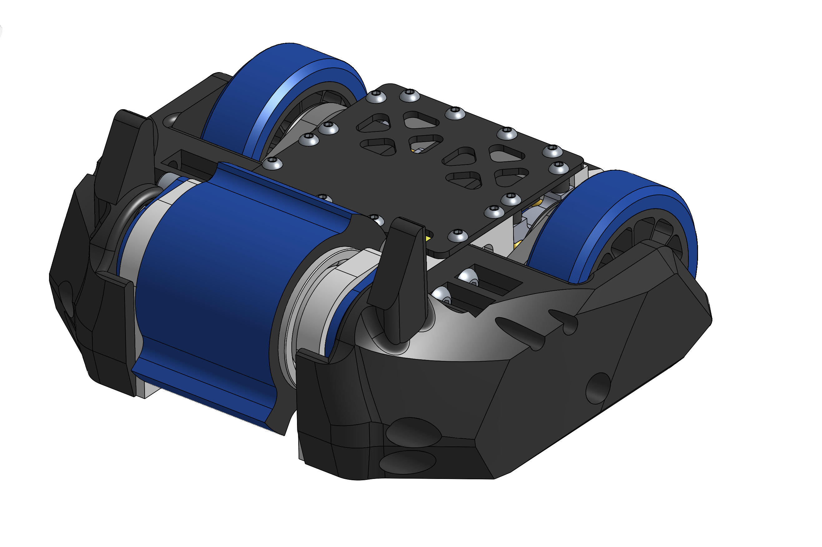
Robot layout
The first two beetle I made has been pretty much the same, weapon in the front, drive motor in the middle and battery in the back. This layout worked pretty well except some minor issues. The frame is so long that when the robot is inverted, the wheels needs to be incredibly big to touch the ground, and they make the center of gravity higher up and destablize the whole robot. Secondly, the track of the robot was pretty small, making the robot turn way too fast.
The new layout I decided to use is to put the battery between the two drive motors and in order to do that I need to use the flattest drive motors and gearboxes possible. I will talk about it later in the article.

Weapon setup
From v3 to v3.5 I was attempting to make a hub motor weapon design. I talked about it a little bit in this article:
https://teambitrobotics.blogspot.com/2022/04/BIT-1.36-v3.4-design-en.html
But I do not like the weapon geometry and there are some radical designs that I think are just too big of a risk to go for. And in 2022 NHRL July event, I found that weapon setups using belts are not necessarily worse than hub motor and all the parts are accessible and easy to repair & replace.
One of the biggest issues I had with my weapon from my second beetle is that the weapon belt keeps slipping because it is not properly tensioned and the weapon pulley is a smooth pulley instead of a timing pulley. It is actually like this on purpose to protect the motor but it seems like I overdid it. This time I will use belt calculator to get the center to center distance right and use 3d printed pulley for the weapon pulley.
The two 40CrNiMoA drums from my second beetle are holding up really well and I don't see a reason not to use them in this robot too.

Another issue we had was the weapon belt is kinda overkill. 10mm wide XL timing belt is not only unnecessarily strong but is also taking up too much space on the weapon shaft. 6mm should be sufficient. This is another reason to go for 3d printed pulley because you can do custom pulley width.

Drivetrain
The drive train on this robot is one of the biggest specialty. Since my first beetle I have been using custom gearboxes from Team ScrapIron. They are relatively affordable and I have been using the same two gearboxes on both of my robot and they never had any issue except a bent output shaft. The only issue is that they are not making it anymore. Of course I can trust its quality and use it again for my third robot, but this is means that once it is damaged it is also the end of the life of the robot.

I looked into some of the gearboxes in the US like fingertech gearbox and Wang gearbox and they are all quite expensive.
And also, I am trying to find the shortest drive setup possible so that can put the battery between them, and none of the gearboxes seems to satisfy the size constraint.
Then I came to an interesting idea: why not making the gearboxes myself? There are plenty of COTS gears I can buy and I can play around with the gearbox packaging to make it satisfy the size constraint. I have always wanted to do internal spur gear on wheels and build the gearboxes into the frame. At first I tried single stage reduction gearbox because it is the most simple structure I can think of, but the maximum reduction I can get is 6:1, which I don't think is enough. Adding a second stage increases the complexity by a lot and there are a lot more things that can potentially go wrong. But I think this is a tradeoff worth making and depending on the design it is not necessarily any weaker.

The gears are embedded into the frame and the only thing that is sticking out into the frame is the motor. The second stage consists of a TPU internal spur gear built into the wheel and and a small brass gear sticking out from the frame on the outside. When there are too much load the gear will simply skip and the gearbox will remain functional. The wear could potentially be a issue but just in a single match it should be fine. The wheels are on a 6mm dead shaft with two bearings holding it. Like the previous two robots, I am planning to make custom silicone wheels.

I used 3mm PU round belts to transmit the power from the rear wheels to the front wheels. I used 2mm ones on the previous robot, and It the front wheel was slipping quite badly.
I need really flat motor to make the geometry work... something like 12mm thick. Also, I need the motor shaft to come out from the back of the motor, so most motors that use bolt as rotor retention would not work. I think have looked into all mainstream small brushless motor manufacture, and there is only one motor that works: T-motor AM30. The stator size is 2504 and it is designed for fixed wing planes, so it is not as powerful as some of the drone motors, but it still should have plenty of power.


It does not actually has shaft coming out from the back of the motor, but there is 3mm shaft coming out from the front, and I can probably push the shaft out and mount it up side down.
Frame
To reduce cost, I decided to use UHMW frame with aluminum standoffs in between. I can maybe use my FRC team's router to cut the frame. The reason why aluminum is might not be the best idea is because tapping aluminum, especially threads as small as m3, can be quite challenging. I was told that wood screw on UHMW is plenty strong so I don't need to worry about tapping. The router we have is a Shapeoko 4 XL, and it can not really do complex part, so I need to try to get all the features on one side. As for the holes on the side, I can use a 3d printed jig and just drill them out by hand.

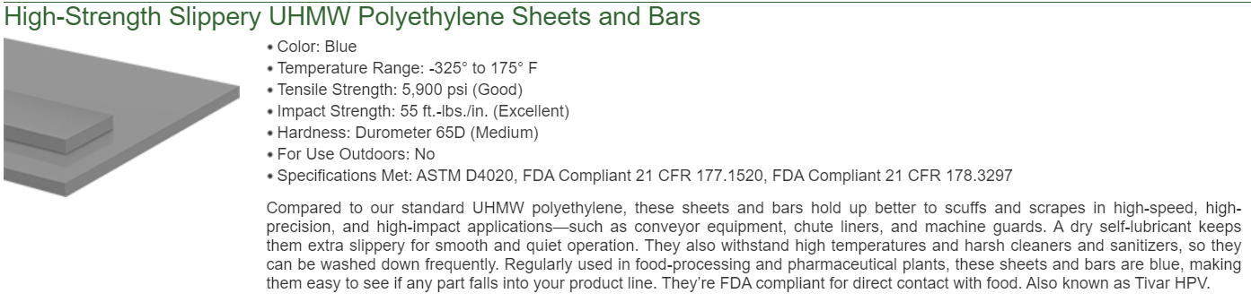
UHMW's density is only half of aluminum, so I arbitrarily decided that the frame should be twice as thick then the aluminum frame I used on the previous robots. All the sheets I can find is in imperial units so the size I decided to use is 5/8". It is also thick enough so that the whole gearbox can be built into the frame.
I found that in Mcmaster, the antistatics UHMW is almost as strong as the high-strength ones, but way cheaper and comes in more sizes, and I guess being antistatic is good for electronics too, so I went with the antistatic ones.


The 64D TPU armor on my second robot did not work superwell. Because of its stiffness, instead of getting small pieces chipped away, what happened was the part got tear apart along the layer lines. This time I bought 95a and 98a TPUs and I will test them out and see which works better.
Electronics
Because I moved away from using smooth aluminum pulley for weapon, there will be way more load on the motor. The weapon motor I am planning to use is Sunnysky 2216 2600kv and has a max current of 57a. On the previous robots, 50a skywalker somehow worked and didn't die even once. I don't think it will be this lucky this time and I think I should start to use the DYS aria 70a. This does mean I need a extra UBEC but I think it is a tradeoff worth making.
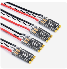
The Drive ESC setup is the same as the previous two robots, two 35a Cyclone ESC. I know it is not really a famous brand but that ESC has not failed me even once.
Battery is once again Tattu 4s 750mAh 95c. It is only 2mm thicker and 1mm longer than 650mAh but gives way more power.

The end
By the time this article is written... the robot has already competed in Clash of the bots 2023. I will write another post about what went good and what went bad. Some of the things that went wrong are rather interesting.
Comments
Post a Comment